![]()
![]()
![]()
![]()
![]()
![]()
FINAL DESIGN REPORT
4.1 Pin Diagrams of 16F877 and BlueCont
4.3 Wiring of our remote controller
7.1 Setting Digital Output Values
Different ways of setting digital output pin values
7.2 Getting Digital Input Values
Different ways of getting digital input pin values
7.3 Setting Analog Output Values
2. Two-pin DAC's with SPI input
4. The way we use: Pulse Width Modulation
7.4 Getting Analog Input Values
8. State Diagram for PIC16F877 Chip
9.1 Pseude Code of the PC Library
9.2 Pseude Code of the Microcontroller
10.1 Tasks to be completed in second semester
Implementation on a sample domain
Customer Evaluation and Final Release
This application provides an interface for the programmers who wish to develop a wireless agent. This interface enables programmers to use wireless protocols even without any background information on RS232 or Bluetooth standards.
One of the most important properties of our solution is its flexibility, that is it can be applied on a variety of domains. It provides 8 digital and 2 analog Input/Output pins, thus it can be used to control a wide range of electronic devices starting from a simple led to a very complex robot.
Since we will develop a wireless environment with Bluetooth communication, we need to parties of Bluetooth supported hardware. For the PC side, we need a Bluetooth dongle which can be provided from any hardware shop. For the remote agent, we need a Bluetooth device with a simple interface. For this purpose, we will use the BlueCont device provided by our university. This device has an RS232 interface which can be used as the communication interface.
Bluetooth Dongle
BlueCont Bluetooth device
The microcontroller which will control the remote agent should have some specifications. We will use PIC 16F877 which satisfies these needs:
Pin Diagram of PIC 16F877
Pin Diagram of BlueCont
VDD pins (11 and 32) and VCC pins (12 and 31) are connected to +5V and Ground, respectively. Memory Clear is connected to 5V with a resistor of 10K ohms. These are the minimum necessary connections to make the microcontroller run.
The oscillator pins are connected to the OSC-In and OSC-Out pins. The oscillator creates the clock ticks with a frequency of 4Mhz.
The B series of pins (33..40) have the capability of supplying high currents. Consequently, we used these pins for digital output purposes. On the other hand D series of pins (19..22 & 27..30) are used for digital input purposes.
Pins A0, A1 and A2 have the ability to behave as analog input. Since we need only two analog input pins, we used only A1 and A2 for this purpose.
For creating analog output voltages, we use the PWM feature of the microcontroller. PIC 16F877 has two PWM pins (16 and 17), so we used these pins with 1 µF capacitors to obtain analog output.
RS232 communication can be obtained by using only two pins. RX(26) and TX(25) pins of the microcontroller are connected to the TX and RX pins of the BlueCont, respectively.


![]()
![]()


Programmer aspect consists of only the programmer. The programmer can control the remote device by only using simple library commands. The only thing the programmer should do is first to design his own project using our remote agent and then control it via simple C functions.
This part includes the controller library and the Bluetooth dongle. First of all, it establishes the connection between the computer and the remote agent. Then it does all the necessary encode operations to transfer the commands of the user to the remote agent, and decode operations to transfer the information sent by the remote agent. Additionally, it calls the pre-defined functions when an interrupt case occurs.
This part includes the BlueCont device, the PIC16F877 microcontroller, the converters and all the I/O pins. The communication between the BlueCont device and the PIC16F877 microcontroller is established by using the RS232 protocol.
The main job of the remote agent is the interaction with the environment. It reads or sets the I/O pins according to the commands received from the programmer. In the main loop, it checks the interrupt cases and if any of them occurs, it informs the computer aspect so that the necessary function can be called.
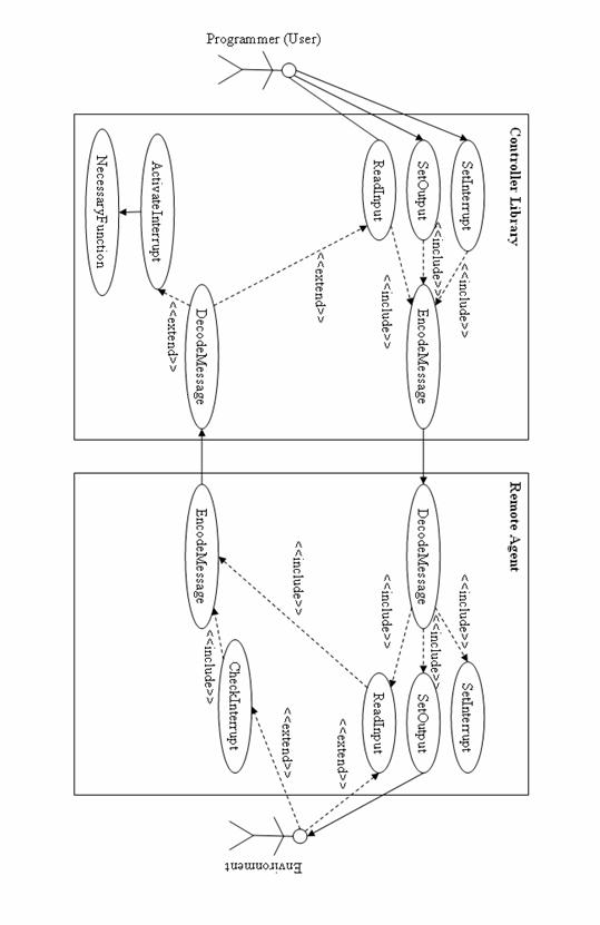
All the communication between the PC and the remote device is established via RS232 interface. To create a virtual RS232 connection between the PC and the BlueCont, these devices should be paired first. This can be done by using the Bluetooth Explorer of Windows. After pairing devices any program can use the serial port assigned by Windows. The initialize() function in our library opens the assigned serial port so that communication between the PC and the remote agent can be established.
The RS232 interrupt feature of the microcontroller helps us to receive a message immediately. Whenever a message comes from the PC side, this interrupt occurs and the microcontroller parses the message to decide what to do.
For example, if the programmer calls the setDigitalOutput(3, 1) after calling the initialize() function, our library on the PC prepares the message SDC31 . Then this message is transferred to the BlueCont via the virtual serial port (actually via Bluetooth). The BlueCont device transfers this message to the microcontroller. When microcontroller receives and parses the message, it sets the digital output pin 3 to high.
For the cases that you set the value of an output pin, the remote agent doesn't need to send back some extra information. But this is not so in the case of reading input pins. When a user calls, for example g etDigitalInput(4) function, our library first sends the necessary message and then waits for an answer message. When it receives the answer message, it returns the parsed value.
For the interrupt cases, a thread will be running on the background. This thread will listen to the serial port if any interrupt alert message is sent by the microcontroller. When an interrupt case occurs, the thread will call the predefined function. For detailed information on interrupts, please refer to the related chapter.
|
Format |
Description |
Constraints |
Direction |
Digital Output |
SDC pv |
Set one digital output pin to a constant value. |
p =[0 .. 8] (id of the pin) v =[0, 1] (value for the pin) |
PC à RA |
SDA v |
Set all the digital output pins according to an 8 bit number |
v =[0 .. 255] (pin values combined in an 8 bit integer) |
PC à RA |
|
SDF pf |
Set one digital output pin to alternate with a constant frequency |
p =[0 .. 8] (id of the pin) f =[1 .. 10.000] (frequency, Hz) |
PC à RA |
|
Digital Input |
GDC p |
Get the current value of a digital input pin. |
p =[0 .. 8] (id of the pin) |
PC à RA |
v |
The value of an input pin |
v =[0, 1] (value of the pin) |
RA à PC |
|
GDA |
Get the current values of all the digital input pins |
|
PC à RA |
|
v |
The values of all the digital input pins combined in an 8 bit integer |
v =[0 .. 255] (value of the pins) |
RA à PC |
|
Analog O. |
SA pv |
Set one digital output pin to a constant value. |
p =[0, 1] (id of the pin) v =[0 .. 255] (0..5 Volt voltage value defined with 8 bit precision) |
PC à RA |
Analog I. |
GA p |
Get the current value of an analog input pin. |
p =[0, 1] (id of the pin) |
PC à RA |
v |
The value of an input pin |
v =[0 .. 255] (0..5 Volt voltage value defined with 8 bit precision) |
RA à PC |
|
Interrupts |
SI i D pv |
Set an interrupt for the case a digital input gets a value |
i =[0 .. 7] (id of the interrupt) p =[0 .. 8] (id of the pin) v =[0, 1] (value for the pin) |
PC à RA |
SI i A pAv |
Set an interrupt for the case an analog input goes above a value |
i =[0 .. 7] (id of the interrupt) p =[0, 1] (id of the pin) v =[0 .. 255] (value for the pin) |
PC à RA |
|
SI i A pBv |
Set an interrupt for the case an analog input falls below a value |
i =[0 .. 7] (id of the interrupt) p =[0, 1] (id of the pin) v =[0 .. 255] (value for the pin) |
PC à RA |
|
IA i |
The alarm message that is sent when an interrupt case occurs. |
i =[0 .. 7] (id of the interrupt)
|
RA à PC |
|
Misc. |
RESET |
Reset all the output pins |
|
PC à RA |
ACK |
Acknowledgement message |
|
RA à PC |
* RA stands for Remote Agent.
Setting the output voltage of a pin is one of the basic futures of PIC microcontrollers. PICC compiler provides output_high() and output_low() functions which are used to set output values of pins.
For example, if the programmer calls the function setDigitalOutput(0, 1), the message SDC01 will be sent to the microcontroller. Then the microcontroller parses the message and makes the necessary function call that is:
output_high(PIN_B0);
Since the second parameter of the message is 1 , the function output_high() is used here. Additionally, the received message states that digital output pin 0(zero) is going to be set, and according to our definitions, B0 pin of the PIC is used as the digital output pin 0. That's why the parameter of the function is PIN_B0 .
Our solution provides different ways of setting digital output values. The first and the simplest way is setting one single output pin to a constant value. Once a pin is set to a certain value, it will not be changed until stated so.
The second way is setting all the output pin values with one single command. This is done by giving an 8 bit integer as a parameter. Each bit of this parameter will be used as the value for each output pin. The least significant bit corresponds to the 0 th output pin and vice versa.
Finally, an output pin can be set to alternate with a constant frequency. If an output pin is set so, it produces a square wave by giving high and low voltages repeating in the defined frequency. For this purpose, timer2 of the microcontroller is used. This timer calls an interrupt in every predefined millisecond, which will alternate the output pin value.
Getting the input voltage of a pin is one of the basic futures of PIC microcontrollers. PICC compiler provides a function called read() that is used to get the input value of a pin.
For example, if the programmer calls the function getDigitalInput(5), the function will send the message GD5 and wait for the result. Then the microcontroller parses the message and makes the necessary function call that is:
v=read(PIN_D5);
Once the value of the pin is stored in the variable v, this value is sent back to the PC. The function getDigitalInput() reads this message and returns this value.
Our solution provides different ways of getting digital input pin values. The first and the simplest way is getting the current value of an input pin.
The second way is getting all the input pin values combined in an 8 bit integer. Each bit of the return value corresponds to the value of an input pin. The least significant bit corresponds to the 0 th input pin and vice versa.
PIC Microcontrollers doesn't provide a built-in analog output feature. But there are 3 different ways of converting digital values to analog voltages.
This is one of the most popular DACs (Digital to Analog Converter). This is a binary weighted DAC that creates each value with a repeating structure of 2 resistor values, R and R times two. This improves DAC precision due to the ease of producing many equal matched values of resistors or current sources, but lowers conversion speed due to parasitic capacitance.
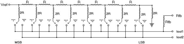
The disadvantage of this DAC is that it requires a large number of pins. For example, if you want an 8 bit precision analog output, it requires 8 pins. Since our product will have 2 analog outputs, we would need at least 16 pins only for analog outputs. That costs much and we will not use this alternative.
These DACs can be obtained as a microchip which includes a built-in ladder circuitry. They use the SPI interface to get the output voltage, so it requires only two pins. In our project, we should provide two analog outputs so we need two SPI interfaces. PIC16F877 provides only one SPI interface and microcontrollers with more than one SPI interfaces are rather expansive, complex and large. So we do not prefer using this alternative either.
Among these popular ones, there are many other alternatives like oversampling DACs, segmented DACs, Hybrid DACs and etc. None of these are the way we prefer.
Being the most new fashion DAC, Pulse Width Modulation(PWM) is the best choice for us. The most important element of these type of DACs is a capacitor. The role of a capacitor here is that it slows down the voltage change in a circuitry. If you change the voltage of a capacitor from high to low and low to high repeatedly, it will produce the average of the input values.
For example, if you provide 5V for 1µs then 0V for 1µs and repeat these infinitely, the capacitor will give an output voltage of 2.5 V. On the other hand, if you provide 5V for 4µs then 0V for 1µs, the capacitor will produce 4V.
The percentage of the high voltages is called the duty of a cycle. The diagram shows some sample cycles.
The output voltage is equal to the high voltage times the duty of the cycle. For the sample cases:
Output voltage of the 20% Duty Cycle is: 5V * 20% = 1.0 Volts
Output voltage of the 50% Duty Cycle is: 5V * 50% = 2.5 Volts
Output voltage of the 80% Duty Cycle is: 5V * 80% = 4.0 Volts
We might have needed to implement pulse width modulation manually, but thanks god PIC 16F877 provides two pins that has the capability of PWM. We only need to define the cycle duty according to the commands came from the programmer.
The message communication process is much similar to that of digital output setting. Because of the limitations of the analog circuitry, we cannot set an analog output pin to alternate with a frequency. We can only define a constant value for an analog pin. As might be expected, the programmer will have the ability to change the output value during an execution but he will not be able to make fast changes.
PIC 16F877 provides a built-in Analog-to-Digital Converter (ADC). For the analog input feature, we will use this property of the microcontroller.
The pins A0, A1 and A2 have the capability of behaving as an analog input. When the microcontroller is turned on, it initially sets these pins to behave as an analog input. After this, reading the values from these pins is as simple as calling a function.

If the programmer wants a function to be called in some predefined cases, he can use interrupt feature of our product.
The possible interrupt cases are listed below:
When the programmer defines an interrupt case, it will be stored in the microcontroller database. The microcontroller can store at most 8 interrupt cases.
For example, if the programmer wants the function foo() to be called in case digital input 3 becomes 0, he can call the function:
setInterrupt(0, DIGITAL, 3, 0, foo);
The first parameter is the id of the interrupt case. Since the microcontroller can check 8 interrupt cases, this parameter is necessary.

At each cycle, the microcontroller checks if any interrupt case is occurred. When an interrupt case occurs, it sends an alarm message to the PC so that the necessary function be called.
Suppose the function foo is set to be called when interrupt case 3 occurs. If the interrupt case 3 occurs, the microcontroller sends an alarm message ( IA3 ) to the PC which states that interrupt case 3 is occurred. When the PC reads the alarm message, it calls the necessary function.
void initialize() {
// Open serial port and establish connection
// Initiate interrupt thread
}
void reset() {
// Reset all the output pins
}
void setDigitalOutput(p, v) {
// Prepare and send the message SDCpv
}
void setDigitalOutputAll(v) {
// Prepare and send the message SDAv
}
void setDigitalOutputFrequency(p, v) {
// Prepare and send the message SDFpv
}
int getDigitalInput(p) {
// Prepare and send the message GDCp
// Wait for the answer message
// Parse the message and return the value
}
int getDigitalInputAll() {
// Prepare and send the message GDA
// Wait for the answer message
// Parse the message and return the value
}
void setAnalogOutput(p, v) {
// Prepare and send the message SApv
}
int getAnalogInput(p) {
// Prepare and send the message GAp
// Wait for the answer message
// Parse the message and return the value
}
void setInterrupt(id, type, p, v, fun) {
// Prepare and send the interrupt setting message
// Create an assignment with id and fun
// in the interrupt database
}
void interruptThread() {
// Listen to the serial port to check
// if an interrupt has occurred
}
void initialize() {
// Initiate rs232interrupt
// Initiate timer2interrupt
// Set A0 and A1 pins to behave as analog inputs
}
void setDigitalOutput(p, v) {
// Set the output voltage of pin p to v
}
int getDigitalInput(p) {
// Return the input value of pin p
}
void setAnalogOutput(p, v) {
// Set the output voltage of pin p to v
}
int getAnalogInput(p) {
// Return the input value of pin p
}
void setInterrupt(id, type, p, v) {
// Update the interrupt database according to
// the parameters
}
void rs232interrupt() {
// Parse the string and call the necessary function
// Send an answer message if necessary
}
void timer2interrupt() {
// Update digital output pins which are set to
// alternate in a frequency rate
}
void mainLoop() {
// Check for all the interrupt cases
// If an interrupt case occurs, send an alarm message
// Send an acknowledgement message periodically.
}
Task Name |
Start |
Finish |
Duration |
Implementation |
|
|
|
Prototype Review |
06.02.2006 |
13.02.2006 |
7 D |
Design for the implementation domain |
13.02.2006 |
20.02.2006 |
7 D |
Implementation Initials and system design |
20.02.2006 |
27.02.2006 |
7 D |
Interface design |
28.02.2006 |
08.03.2006 |
9 D |
Implementation |
01.03.2006 |
15.03.2006 |
15 D |
Integration of components |
11.03.2006 |
16.03.2006 |
5 D |
Testing |
17.03.2006 |
21.03.2006 |
4 D |
Debugging |
23.03.2006 |
29.03.2006 |
6 D |
Documentation |
|
|
|
Web Design |
15.03.2006 |
21.03.2006 |
6 D |
Developer Guide |
18.03.2006 |
24.03.2006 |
6 D |
User Manual |
25.03.2006 |
29.03.2006 |
4 D |
Installation Manual |
27.03.2006 |
31.03.2006 |
4 D |
Customer Evaluation and Feedback |
|
|
|
First Customer Release |
03.04.2006 |
07.04.2006 |
4 D |
Customer Reviews |
17.04.2006 |
21.04.2006 |
4 D |
Final Release |
24.04.2006 |
08.05.2006 |
|