![]()
![]()
![]()
![]()
![]()
![]()
2.5. Remote Controllable Toy Car
3.2. Documentation Requirements
3.3. PIC Programming Requirements
3.4. Interface Programming Requirements
4.1.2.4. Signal rate selection
4.2. Bluetooth Wireless Technology
We are planning to design a remote controller for a device. The device will be a moving device that looks like a car. We intended to make an exploring device like the pathfinder. This device will be controlled from a distant computer by using a program that we implemented. This device will have the following functionalities.
• Our device will have the capability to move on any direction. The user will determine the direction that he wants the device to move and then on the computer by clicking on a button make the device go forward, backward, left or right.
• Our device will have the capability to speed up and down. When the user click on the speed up/slow down button the device will increase/decrease its speed.
• Our device will have the capability to send a signal when it crashes to a wall or any other barriers. The user will be informed about this on the screen.
• Our device will have the capability to take photos. When the user wants to take the photo of the environment, by clicking on the photo button he will see the photo on the screen that is taken by a small camera which is located on the device.
The user interface that we will implement to control the device from our computer will have the following properties.
• There will be front, back, left and right buttons to make the device go through these directions.
• There will be speed up and slow down buttons to increase the speed of the device or decrease the speed of the device. when the speed is zero then the device will stop.
• The speed of the device will be displayed on the screen.
• The information about a crash will be displayed on the screen.
• There will be a photo button which is used to order the device to take the photo of the environment.
• The photo will be displayed on the screen.
• There will be a save button to save the photo that is taken from the device.
In order to make our device and succeed our task the following hardware components are required. We couldn't get some of the hardware devices but we made some researches on the internet and from books about the devices that we will buy and get from the department.
To increase mobility, we plan to use laptop computer. Any laptop with modest configuration will be adequate . To make it more concrete we may say that a computer with these configuration would be enough for all needs :
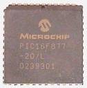
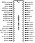
In order to convert Bluetooth signals to hardware commands, we are going to use a programmable integrated circuit. Because of its wide capabilities we are going to use Microchip 16F877.Some specifications of it are :
PROPERTIES |
PIC16F877 |
Working Speed |
DC-20Mhz |
Programming Memory |
8Kx14 word Flash ROM |
EEPROM Memory |
256 byte |
User RAM |
368 x 8 byte |
Input / Output port number |
33 |
Timer |
Timer0, Timer1, Timer2 |
A / D translator |
8 channel 10 bit |
Capture / Comp / PWM |
16 bit Capture 16 bit Compare 10 bit PWM resolution |
Serial Peripheral Interface |
SPI (Master) and SPI port on mode 12C (Master / Slave) (synchronous serial port) |
Paralel slave port |
8 bit, with external RD,WR and CS control |
USART / SCI |
9 bit addressable |
This card will be provided by our department. We have not seen this yet but we tried to search about this card on the internet and found some data about it. It will probably a card like the one below.
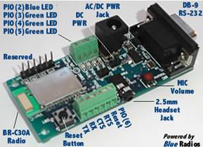
Some properties of this card are; Class1 with audio codec, jack, and volume control for voice operation, 0-3.3Vdc levels & RS232 inputs. 1Mbps RS232 UART
Outline
Wireless data and voice communications module certified to Bluetooth v1.2
Audio codec, head jack, head phones, MIC volume control.
FCC, CE, Industry Canada , and Bluetooth certified ISM 2.4GHz band module.
RS-232 (DB-9), and 0-3.3 Vdc logic levels
Include integrated software stack, profiles, and AT modem like commands.
Embedded Bluetooth Stack Profiles included (requires no host MCU stack):
SPP, DUN, LAN, PAN, Headset, Audio Gateway, FTP, GAP, SDP, RFCOMM, and L2CAP protocols.
Evaluation Board Accommodates both BR-C30A and BR-C29A radio modules.
Features
The BlueRadios serial radio modems can be configured, commanded, and controlled through simple ASCII strings over the Bluetooth RF link or directly through the hardware serial UART.
Dedicated PCM voice audio channel
UART band rate data speeds: 1200bps up to 921.6 Kbps, and customized
+100 meter (330 feet) distance
Software adjustable transmitter power from short to long range applications
Includes AC/DC power supply
13 bit linear mono CODEC
Programmable Input Output (PIO`s)
Reset push button
LED status: Power Bluetooth Connection, Slave Status, etc.
2.5mm audio jack
Low power consumption (120mA TX, 40mA RX, 2mA idle mode, and 90uA deep sleep)
RS-232 and 3.3Vdc TTL inputs
Self-discovery and network equipped multi-points
Operating temperature range: -40 +70 C
Secure and robust communication link.
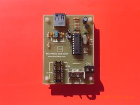
With this card the microcontrollers with 8 and 18 pins having flash memory can be programmed by placing them to the socket of the card. Other 28 and 40 pinned pic microcontrollers have problems while placing to and removing from the socket because of their extra pins. For this reason there is another socket ICSP on the card. By making the related connections the 28 and 40 pinned microcontrollers can be programmed too.
16F877 can be programmed by this card.
2.5. Remote Controllable Toy Car
This is our device that will be controlled by our microcontroller. The microcontroller will be embedded on it. We decided to make it buy a toy car because of its functional sufficiency and it is easier to buy it than designing it.
A standard web cam will be enough to meet our needs. This will be used for taking photos of the environment and it will be embedded to our car.
We are going to use Windows XP as operating system.
3.2. Documentation Requirements :
Microsoft Office 2003 Word will be used for word processing and Microsoft Office Visio 2003 Professional and Microsoft Office PowerPoint 2003 for developing required diagrams and charts, and for presentation needs.
3.3. PIC Programming Requirements :
PIC may be programmed using Assembly Language, C or Basic. Since controllers with Basic compilers are extremely expensive, we discard Basic option. Because of the fact that we are more familiar with C programming than assembly programming and Assembly source codes are more difficult to manage, we plan to use PIC C programming.
We will disassemble C codes and embed them to the PIC via the converter .
3.4. Interface Programming Requirements :
We are going to use Sun Microsystems Java for graphical user interface programming because of its flexibility and wide package archive. Thus we need J2SE 1.4.2 SDK which is available from java.sun.com without any cost. Because of its platform independency our interface will be able to run on both Windows and Unix-based systems.
3.5. Web design Requirements :
We are going to use PHP for our web design. The main reason for choosing PHP is that we have a background about this language. Another reason why we selected PHP is being a widely used general-purpose scripting language which is especially suited for web development and can be embedded into HTML.
In telecommunications, RS-232 is a standard for serial binary data interconnection between a DTE (Data terminal equipment) and a DCE (Data communication equipment). It is commonly used in computer serial ports.
The EIA standard RS-232-C as of 1969 defines:
The standard does not define such elements as character encoding (for example, ASCII, Baudot or EBCDIC), the framing of characters in the data stream (bits per character, start/stop bits, parity. The standard does not define bit rates for transmission, although the standard says it is intended for bit rates less than 20,000 bits per second. Many modern devices can exceed this speed (38,400 and 57,600 bit/s being common, and 115,200 and 230,400 bit/s making occasional appearances) while still using RS-232 compatible signal levels.
In RS-232, data is sent as a time-series of bits. Both synchronous and asynchronous transmissions are supported by the standard. The standard does not define character framing within the data stream, or character encoding.
The RS-232 standard defines the voltage levels that correspond to logical one and logical zero levels. Signals are plus or minus 3 to 15 volts. The range near zero volts is not a valid RS-232 level; logic one is defined as a negative voltage, the signal condition is called marking, and has the functional significance of OFF. Logic zero is positive, the signal condition is spacing, and has the function ON. The standard specifies a maximum open-circuit voltage of 25 volts; signal levels of ±5 V, ±10 V, ±12 V, and ±15 V are all commonly seen depending on the power supplies available within a device. Circuits driving an RS-232-compatible interface must be able to withstand indefinite short circuit to ground or to any voltage level up to 25 volts. The slew rate, or how fast the signal changes between levels, is also controlled.
RS-232 devices may be classified as Data Terminal Equipment (DTE) or Data Communications Equipment (DCE); this defines which wires will be sending and receiving each signal. In general, terminals have male connectors with DTE pin functions, and modems have female connectors with DCE pin functions. Other devices may have any combination of connector gender and pin definitions. The standard specifies 20 different signal connections. The following table lists the commonly used RS-232 signals and common pin assignments:
Signal |
DB-25 |
DE-9 |
EIA/TIA 561 |
Yost |
Common Ground |
7 |
5 |
4 |
4,5 |
Transmitted Data (TD) |
2 |
3 |
6 |
3 |
Received Data (RD) |
3 |
2 |
5 |
6 |
Data Terminal Ready (DTR) |
20 |
4 |
3 |
2 |
Data Set Ready (DSR) |
6 |
6 |
1 |
7 |
Request To Send (RTS) |
4 |
7 |
8 |
1 |
Clear To Send (CTS) |
5 |
8 |
7 |
8 |
Carrier Detect (DCD) |
8 |
1 |
2 |
7 |
Ring Indicator (RI) |
22 |
9 |
1 |
- |
The signals are labeled from the standpoint of the DTE device; TD, DTR, and RTS are generated by the DTE and RD, DSR, CTS, DCD, and RI are generated by the DCE.
Connecting a fully-standard-compliant DCE device and DTE device would use a cable that connects identical pin numbers in each connector (a so-called "straight cable"). "Gender changers" are available to solve gender mismatches between cables and connectors. Connecting devices with different types of connectors requires a cable that connects the corresponding pins according to the table above. Connecting two DTE devices together requires a null modem that acts as a DCE between the devices by swapping the corresponding signals (TD-RD, DTR-DSR, and RTS-CTS). This can be done with a separate device and two cables, or using a cable wired to do this. For configuring and diagnosing problems with RS-232 cables, a "breakout box" may be used. This device normally has a female and male RS-232 connector and is meant to attach in-line; it then has lights for each pin and provisions for interconnecting pins in different configurations. RS-232 cables may be built with connectors commonly available at electronics stores. The cables may be between 3 and 25 pins; typically 4 or 6 wires are used. Flat RJ (phone-style) cables may be used with special RJ-RS232 connectors, which are the easiest to configure. While the control lines of the RS 232 interface were originally intended for call setup and takedown, other "handshakes" may be required by one or the other device. These are used for flow control, for example, to prevent loss of data sent to a serial printer. For example, pin 20 is commonly used to indicate "device ready". Pins may also be "jumpered" or routed back within the connector. For example a pin saying "are you ready?" from device A might be wired to the pin saying "I'm ready" on device A if device B did not transmit such a signal. Common handshake pins are 20, 8, 4, and 6.
The DTE or DCE can specify use of a "high" or "low" signaling rate. The rates as well as which device will select the rate must be configured in both the DTE and DCE. The prearranged device selects the high rate by setting pin 23 to ON.
Many DCE devices have a loopback capability used for testing. When enabled, signals are echoed back to the sender rather than being sent on to the receiver. If supported, the DTE can signal the local DCE (the one it is connected to) to enter loopback mode by setting pin 18 to ON, or the remote DCE (the one the local DCE is connected to) to enter loopback mode by setting pin 21 to ON. The latter tests the communications link as well as both DCE's. When the DCE is in test mode it signals the DTE by setting pin 25 to ON.
The timing signals are provided by the DCE on pins 15 and 17. Pin 15 is the transmitter clock; the DTE puts the next bit on the data line (pin 2) when this clock transitions from OFF to ON (so it is stable during the ON to OFF transition when the DCE registers the bit). Pin 17 is the receiver clock; the DTE reads the next bit from the data line (pin 3) when this clock transitions from ON to OFF. Alternatively, the DTE can provide a clock signal on pin 24 for both transmitted and received data. Again, data is changed when the clock transitions from OFF to ON and read during the ON to OFF transition.
Data can be sent over a secondary channel (when implemented by the DTE and DCE devices), which is equivalent to the primary channel. Pin assignments are described in following table:
Signal |
Pin |
Common Ground |
7 (same as primary) |
Secondary Transmitted Data (STD) |
14 |
Secondary Received Data (SRD) |
16 |
Secondary Request To Send (SRTS) |
19 |
Secondary Clear To Send (SCTS) |
13 |
Secondary Carrier Detect (SDCD) |
12 |
4.2 Bluetooth Wireless Technology
The Bluetooth Specification defines a short (around 10 m) or optionally a medium range (around 100 m) radio link capable of voice or data transmission to a maximum capacity of 720 kbps per channel.
Radio frequency operation is in the unlicensed industrial, scientific and medical (ISM) band at 2.4 to 2.48 GHz, using a spread spectrum, frequency hopping, full-duplex signal at up to 1600 hops/sec. The signal hops among 79 frequencies at 1 MHz intervals to give a high degree of interference immunity. RF output is specified as 0 dBm (1 mW) in the 10m-range version and -30 to +20 dBm (100 mW) in the longer range version.
When producing the radio specification, high emphasis was put on making a design enabling single-chip implementation in CMOS circuits, thereby reducing cost, power consumption and the chip size required for implementation in mobile devices.
4.2.1 Voice
Up to three simultaneous synchronous voice channels are used, or a channel which simul-taneously supports asynchronous data and synchronous voice. Each voice channel sup-ports a 64 kb/s synchronous (voice) channel in each direction.
4.2.2 Data
The asynchronous data channel can support maximal 723.2 kb/s asymmetric (and still up to 57.6 kb/s in the return direction), or 433.9 kb/s symmetric.
• A Master can share an asynchronous channel with up to 7 simultaneously active slaves in a Piconet.
Slaves can participate in different piconets and a master of one Piconet can be the slave in another, this is known as a Scatternet. Up to 10 piconets within range can form a Scatternet, with a minimum of collisions.
4.2.3 Network Architecture
Bluetooth units that come within range of each other can set up ad hoc point-to-point and/or point-to-multipoint connections. Units can dynamically be added or disconnected to the network. Two or more Bluetooth units that share a channel form a piconet.
Several piconets can be established and linked together in ad hoc scatternets to allow communication and data exchange in flexible configurations. If several other piconets are within range they each work independently and each have access to full bandwidth. Each piconet is established by a different frequency hopping channel. All users participating on the same piconet are synchronized to this channel. Unlike infrared devices, Bluetooth units are not limited to line-of-sight communication.
To regulate traffic on the channel, one of the participating units becomes a master of the piconet, while all other units become slaves.With the current Bluetooth Specification up to seven slaves can actively communicate with one master. However, there can be almost an unlimited number of units virtually attached to a master being able to start communication instantly.
4.2.4 Hardware Architecture
The Bluetooth hardware consists of an analog radio part and a digital part - the Host Con-troller. The Host Controller has a hardware digital signal processing part called the
Link Controller (LC), a CPU core and interfaces to the host environment. The Link Controller consists of hardware that performs baseband processing and physical layer protocols such as ARQ-protocol and FEC coding. The function of the Link Controller includes Asynchronous transfers, Synchronous transfers, Audio coding and Encryption.
The CPU core allows the Bluetooth module to handle Inquiries and filter Page requests without involving the host device. The Host Controller can be programmed to answer cer-tain Page messages and authenticate remote links.
The Link Manager (LM) software runs on the CPU core. The LM discovers other LMs and communicates with them via the Link Manager Protocol (LMP) to perform its service provider role and to use the services of the underlying Link Controller. Ericsson offers complete packages of intellectual property (IP) that support both Bluetooth core and Bluetooth radio chip development.
4.2.5 Software Architecture
The Bluetooth protocols are marked with blue color in the illustration below. In order to make different hardware implementations compatible, Bluetooth devices use the Host Controller Interface (HCI) as a common interface between the Bluetooth host (e.g. a por-table PC) and the Bluetooth core.
Higher level protocols like the Service Discovery Protocol (SDP), RFCOMM (emulating a serial port connection) and the Telephony Control protocol (TCS) are interfaced to baseband services via the Logical Link Control and Adaptation Protocol (L2CAP). Among the issues L2CAP takes care of, is segmentation and reassembly to allow larger data packets to be carried over a Bluetooth baseband connection.
The service discovery protocol allows applications to find out about available services and their characteristics when e.g. devices are moved or switched off.
Crein currently uses a generic software that includes HCI Driver, L2CAP, RFCOMM and SDP to be integrated in a host environment by Ericsson.
• wikipedia, free encyclopedia, RS232 link, http://en.wikipedia.org/wiki/RS-232
• Bluetooth Wireless Technology, http://www.bilkent.edu.tr/eee
• PIC PROG USB/ICSP, http://www.dundarelektronik.com.tr
• PIC16F877 / SAYI 1, http://www.altaskitap.com
• Evaluation Kit, http://www.blueradios.com