![]()
![]()
![]()
![]()
![]()
![]()
5. Descriptions of System Aspects
7.4 State Diagram for PIC16F877 Chip
In this initial design report we present a basic model of our solution to understand and explain the system better. In addition to this , this initial design will constitute the basis for final design and implementation of the system.
We have added project schedule and illustrative diagrams such as deployment diagram, use case diagram , communication (collaboration) diagrams and state diagram to make the topic and development stages more concrete .
Topics discussed here will be more deeply emphasized on the final design report which will be an extended version of this report including any needed revisions on this report and much more detiled implementation plan.
This application provides an interface for the programmers who wish to develop a wireless agent and enables programmers to use wireless protocols even without any background information on RS232 or Bluetooth standards.
Our solution will provide:
One of the most important properties of our solution is its flexibility , that is it can be applied on a variety of domains. It provides 8 digital and 2 analog Input/Output pins, thus it can be used to control a wide range of electronic devices starting from a simple led to a very complex robot.
Using our solution our customers , which will be basically composed of programmers and electronic device developers , will be able to design wireless solutions with great ease.
Tasks to be completed:
• Bluetooth data transfer format
• Basic PIC applications
• Circuit design of the hardware
• Interface I
• Interface II
• Interface III
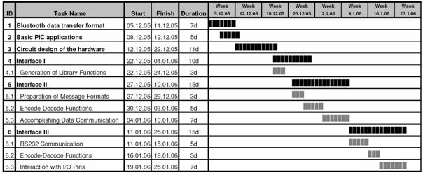
Design and Implementation on a sample domain
Programmer aspect consists of only the programmer. The programmer can control the remote device by only using simple library commands. The only thing the programmer should do is first to design his own project using our remote agent and then control it via read and write commands.
This part includes the controller library and the Bluetooth dongle. First of all, it establishes the connection between the computer and the remote agent. Then it does all the necessary encode operations to transfer the commands of the user to the remote agent, and decode operations to transfer the information sent by the remote agent. Additionally, it calls the pre-defined functions when an interrupt case occurs.
This part includes the BlueCont device, the PIC16F877 microcontroller, the converters and all the I/O pins. The communication between the BlueCont (abbreviation for Bluetooth hardware) device and the PIC16F877 microcontroller is established by using the RS232 protocol.
The main job of the remote agent is the interaction with the environment. It reads or sets the I/O pins according to the commands received from the programmer. In the main loop, it checks the interrupt cases and if any of them occurs, it informs the computer aspect so that the necessary function can be called.
This is the interface between the programmer and the controller library. The programmer can access the remote agent through this interface. This interface enables programmers to:
This is the interface between the controller library and the Bluetooth dongle which is connected to the computer. It basically establishes the communication and the collaboration between these two components. Main functionalities of the interface are:
This is the interface between the BlueCont device and the PIC microcontroller. It is used to apply the commands received from the computer aspect and report the changes on the inputs back. Main functionalities of the interface are:
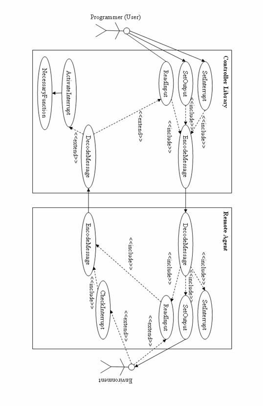

Figure 1 . Communication Diagram for Setting the Values of Digital Outputs

Figure 2. Communication Diagram for Setting the Values of Analog Outputs

Figure 3. Communication Diagram for Reading the Values of Digital Inputs
Figure 4. Communication Diagram for Reading the Values of Analog Inputs

Figure 5. Communication Diagram for Setting the Values of Digital Outputs

Figure 6. Communication Diagram for Setting the Values of Digital Outputs